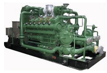
MACHINES, EQUIPMENT AND TECHNOLOGIES IN THE BIOGAS LINE IN WWTP
A wastewater treatment plant (WWTP), also called a purification plant, has the generic objective of achieving, from black or mixed water and through different physical, chemical and biotechnological procedures, effluent water with better quality and quantity characteristics based on standardized parameters.
In general, wastewater treatment plants treat local wastewater mostly from citizen consumption. They also treat wastewater from surface runoff from drainage in urbanized areas and water from small cities through more or less complex and standardized processes or treatments.
Water purification manages to extract contamination from the water at the expense of energy consumption, but it produces the concentrated waste of everything the water contains. These by-products are those from the primary treatment (except for the sludge obtained from the primary settling) that can be assimilated into solid urban waste (garbage). The sludge from the settling receives a special treatment (thickening, digestion, dehydration) until it can be treated as solid urban waste or incinerated, or a by-product capable of being reused as fertilizer in agriculture or other uses after other treatments such as stabilization or composting.
This article describes those machines, equipment and accessories recommended in a biogas production facility, from the digestion of sludge from a WWTP for its use as biofuel to meeting the energy needs (steam-electricity) of the process itself.
DEVELOPMENT .
The digestion of sludge, when carried out anaerobically, produces biogas, which is a mixture of gases containing CH4 (which is what gives it its character as a biofuel and contaminant). The best management option for this gas is to produce energy to meet the energy needs of the plant itself, both in the form of thermal energy (the sludge needs to be at a certain temperature to be digested) and in the production of electrical energy (usable for the electrical consumption of the plant) and the surplus for sale to the electricity sector. In the case of WWTPs, it is also necessary to add particles, sediments, condensates and typical foams in biogas from anaerobic digesters to the impurities or contaminants that biogas has.
In general terms, a biogas installation in a WWTP has the following stages:
- Production/generation of biogas. Anaerobic sludge digestion system.
- Collection and storage. Cleaning/conditioning.
- Generation/use of biogas.
Machines , equipment and accessories in biogas faclities in a wastewater treatment plant (WWTP).
The biogas from the WWTP sludge biodigestion process is a dirty gas that incorporates traces of solid particles, moisture and foam. To prevent these types of materials from reaching the gasometer (biogas receiver) and the machines involved in their transport and use, it is necessary to install the equipment on the line that is detailed below.
Besides being a complex gas in terms of its composition, biogas is also a complex gas in terms of its flow, mainly when it leaves the biodigester given the possible phases involved in its flow. These phases are generally: gaseous, steam (water) and foams. Therefore, this flow can be said to be, in terms of phases involved, biphasic or triphasic.
Foam breakers/separators . The presence of foams, which can be thick from millimetres to more than one meter, can negatively affect plant operation in different ways. In extreme cases, when the foam content exceeds the height available inside the reactor, it can overflow and join the generated biogas flow, creating different problems in the biogas transport line, its instrumentation and accessories. For the elimination of foam in the biogas stream, foam breakers are usually used, generally located in the pipe at the outlet of the reactor. These, in turn, serve as retainers for sediments coming from the reactor.
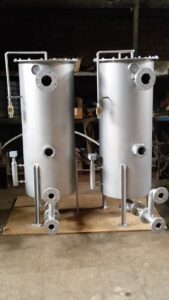
gravel filter It is used in the case of biogas for the separation of solid particles, possible foam, dirt and condensate from the digester. Its operating principle is simple and consists of passing the biogas through a bed of sand of a certain size that serves as a separator of all the impurities contained in the biogas. The condensate is extracted through the lower part of the equipment, and the foam and particles are retained in the gravel bed while the gas leaves through the upper lateral part of the filter.
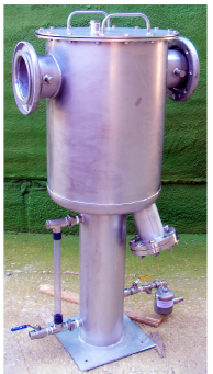
Ceramic filter . It is used for the removal of fine solid particles [150–210 µm]present in the biogas that comes from the anaerobic digestion process and the condensation of excess moisture. Its fundamental part is made up of ceramic cartridges or candles of predetermined pore size. These cartridges are located inside a hermetic cylinder with a support plate for them.
Gasometer . Gasometers are gas storage devices widely used today to store biogas from anaerobic digestion of water treatment plants. These can be of different types according to the work and construction pressure. Floating bell and double-membrane gasholders are the most used for the storage and distribution of biogas to different consumers.
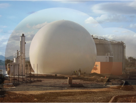
H2S reduction/elimination . The biogas produced in the WWTP wastewater treatment plants is characterized by a high concentration of H2S given the organic load of the sludge. This concentration is included in the range of values from 1000 to 4000 ppm in general. For this reason, to make use of biogas, it is necessary to reduce the concentration of H2S below 250 ppm in the case of electricity generation via motors. Turbines are more permissible in this regard
Several methods (chemical, physical and biological) of H2S removal currently exist. However, one of the most widely used, due to its technical advantages and operating costs, is the biological process, where trickling biofilters or biological scrubbers (bio scrubbers) are used. This process is supported by the addition of O2, H2O and nutrients to a bed through which the biogas circulates. The bacterial culture responsible for eliminating most of the hydrogen sulfide (H2S) contained therein develops in this bed.
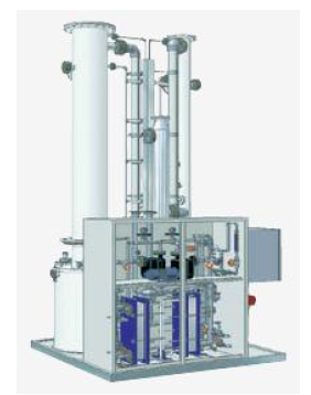
In this process, a nutritive solution is injected, which is recirculated in the packaging for its irrigation and the supply of nutrients to the bacteria formed there. This nutrient solution is usually liquid artificial fertilizer (NPK 886). Special aerobic bacteria, which cause oxidation of H2S (eg Thiothrix or Thiobacillus), begin to grow in the reactor and the nutrient solution. Under the conditions that occur there, the H2S in the gas converts to elemental sulfur and later to sulfuric acid according to the following chemical equations:
- H2S + 2O2 → H2SO4
- 2H2S + O2 → 2S + 2H2O
- S + H2O + 1’5O2 → H2SO4
The main advantages can be summed up as:
- High efficiency: H2S reduction up to 98%. Initial H2S concentrations up to 1.5 vol. % in biogas.
- High flexibility: due to its operating principle and automatic control system, the plant can be applied for a wide range of biogas productions and H2S concentrations without construction modifications.
- Low costs: low investment costs compared to other technologies. No consumption of chemical products except for the nutrient (fertilizer).
- High safety: due to special safety features, risks are avoided, and the amount of air supply is strictly related to the actual gas flow.
Disadvantages.
- High sensitivity to changing operating conditions.
- Tendency to clogging of the bed, packed bed, by deposition of elemental sulfur that is formed on many occasions.
- It requires high control in the injection of air to avoid the risk of explosion.
- It changes the composition of the biogas by the injection of air that it requires. Reduces the methane content, which influences the reduction of the PCI of Biogas.
- Long time to start up.
In this case (process), a packed tower is used, similar to the one used in chemical processes. The control of the liquid level, as well as the amount of O2 injected using the air to avoid explosive mixture with the biogas, etc. is important in the process.
Condensate pots. The biogas from the desulfurization stage is a wet gas given the vapour-liquid balance that exists when the biogas comes into contact with the washing water. For this reason, before entering the dehumidification stage, it is recommended the elimination of excess humidity (water) to minimize the energy consumption of the operation. These condensate traps are hermetic containers where the biogas expands and changes direction to facilitate the elimination of said humidity (variation of the amount of movement).
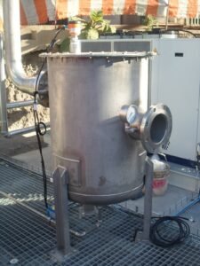
Dehumidifier . The dehumidification of biogas via cooling-condensation is an important stage in the conditioning/treatment of biogas for its future use as biofuel. It has two fundamental elements: a refrigeration machine and a heat exchanger/condenser. In the latter, moisture below 50% is removed from the biogas and, depending on the type of siloxanes and the operating temperature, the total removal of these components can be achieved.
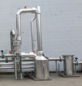
Some drying systems incorporate an internal washing system with the condensate produced itself, which produces a partial elimination of components such as NH3 and H2S present in the biogas. Others incorporate a biogas cold recovery system to minimize the energy consumption of the refrigeration machine.
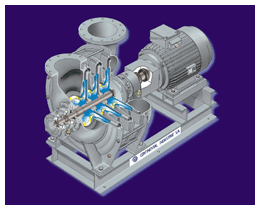
Flow machine . The flow machines used for this case in question are the blowers, which have the function of increasing the pressure of the biogas to reach the different consumers (engines, boilers, torches, etc.) with enough energy for their use. Two types of machines fundamentally appear on the market:
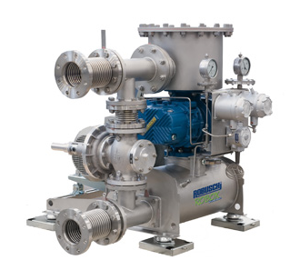
- Positive displacement machines . Lobe and paddle type.
- Rotodynamic machines . 1. Single/multi-stage centrifugal type and 2. Side channel type.
Among the most used blowers for this type of application are multi-stage centrifugal blowers and side channel blowers, depending on the flow rate and pressure. When high pressures are required, it is advisable to use lobe type machines.
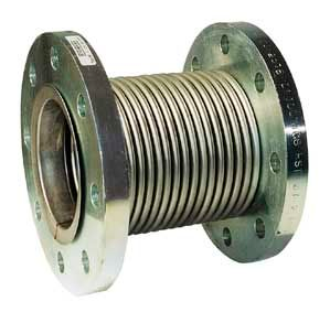
It is recommended that the flow machines used for the transport (pumping) of biogas have the following accessories installed. Expansion joints . They are devices whose purpose is to absorb the thermal expansions that are produced by the increase in temperature of the pumped fluid. Given that in the blower, as a result of the increase in pressure, a thermal jump is produced in the biogas (increase in its temperature), the use of this device is recommended, both at the entrance and the exit of the machine to avoid possible damage to the installation.
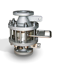
Flame arrester / Flame arrester . To protect the process units, deflagration-proof flame arresters are equipment used in handling systems for explosive mixtures, such as biogas, to mitigate deflagrations. They reliably suppress the effect of deflagrations in pipelines near a potential ignition source (blowers), extinguish the flame and protect systems that cannot withstand the pressure of an explosion.
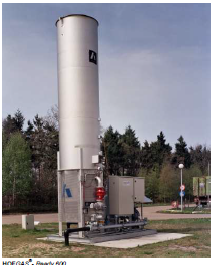
Torches. They are equipment used for the combustion of gases, in this case, the excess biogas from the anaerobic digestion system or the cogeneration system. The torches can be classified into two fundamental types of flame: visible flame and hidden flame.
Active carbon filter . They are widely used for gas cleaning of different types of contaminants. In the case of biogas, they are mainly used for the removal of H2S, siloxanes and halogenated hydrocarbons (Cl and F) present in biogas. Its operation is simple and is based on physical-chemical processes, for which the biogas current is passed through a bed of activated carbon previously selected for the type of compound to be eliminated. These pieces of equipment generally operate in parallel, that is, while one is in operation the other is in maintenance/standby.
For optimum operation of this equipment, prior conditioning of the biogas is required to reduce its moisture content and reduce the temperature as little as possible. Adequate distribution of the biogas inside the filter is also of great interest to avoid any dead zone in it. Therefore, the design of the filter and its free spaces play a fundamental role in this aspect.
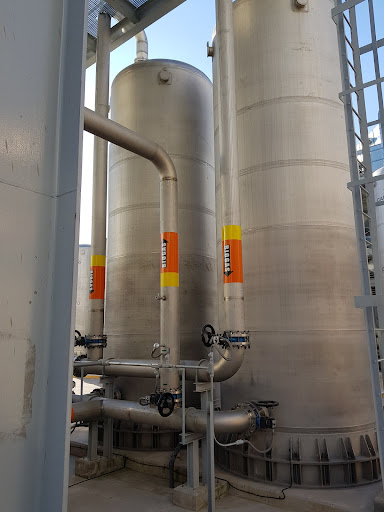
Biogas cleaning/Technologies. For an adequate use of biogas as a biofuel for the generation of energy (thermal or electrical), it is necessary to eliminate different dangerous components (Siloxanes, H2S and hydrocarbons, among others) for the machines involved in this purpose. It is recommended, in turn, to reduce the humidity of the biogas below 50% to promote better use of the energy contained in the biogas.
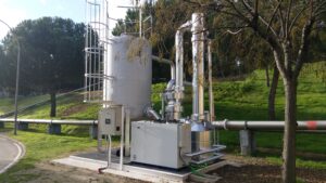
Generation station/Cogeneration system (CHP System) . Depending on the energy needs of the process (heat and/or electricity) and the interests of the WWTP exporting electricity, one equipment or another will be used for the exploitation/use of biogas.
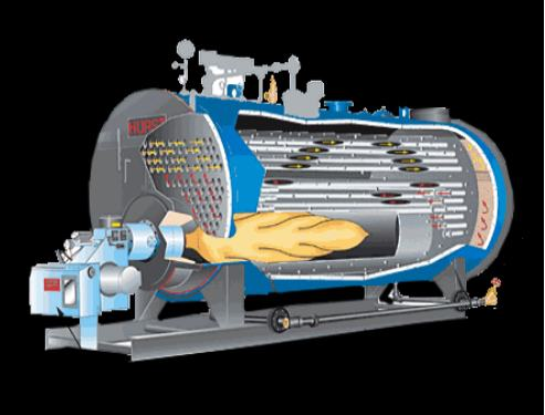
Steam generation . For this, steam boilers are used with a burner adapted to it to work with the biogas to be consumed.
Enter the requirements for its use in a boiler: the flow rate and the pressure necessary to enter the burner. Before the biogas enters the burner, prior purification is required through a steel wool filter and condensate removal in order to prevent corrosion.
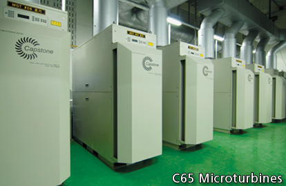
Generation of electricity/heat. Gas engines and turbines . They are flow machines in charge of transforming the chemical energy contained in the biogas into mechanical energy for the production of electricity and heat. The choice of one or the other depends on several factors, among which we can mention: characteristics of the biogas, flow to be treated, desired yields, as well as the interest in the combined production of heat and/or electricity, etc.
